
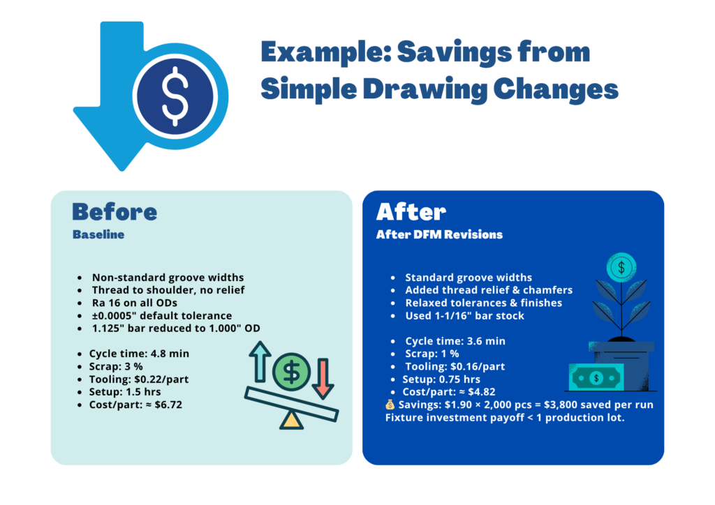
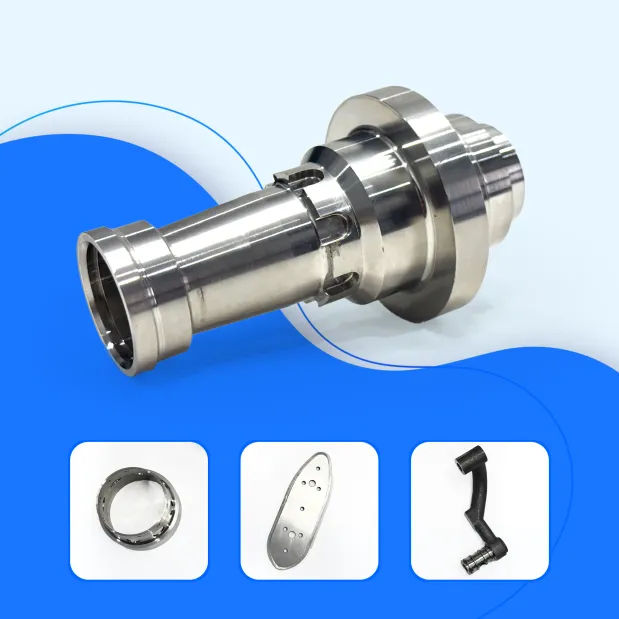
Turned parts get cheaper and more reliable when designs align with how lathes actually cut. Symmetry, standard feature sizes, realistic tolerances, chip-friendly grooves, proper thread reliefs, chamfers, stable L/D ratios, and stock sizes matched to finish ODs all directly influence cycle time, scrap, and tooling life. This guide explains how to apply these principles — with examples, quick math, and a real cost-reduction case study.
Simplify Costs
Use quick formulas to estimate cycle time and part cost.
Tool Efficiency
Match grooves and widths to catalog insert standards.
Design Smarter
Choose standard sizes and realistic, function-based fits.
Save Money
Turn small drawing changes into real, repeatable savings.
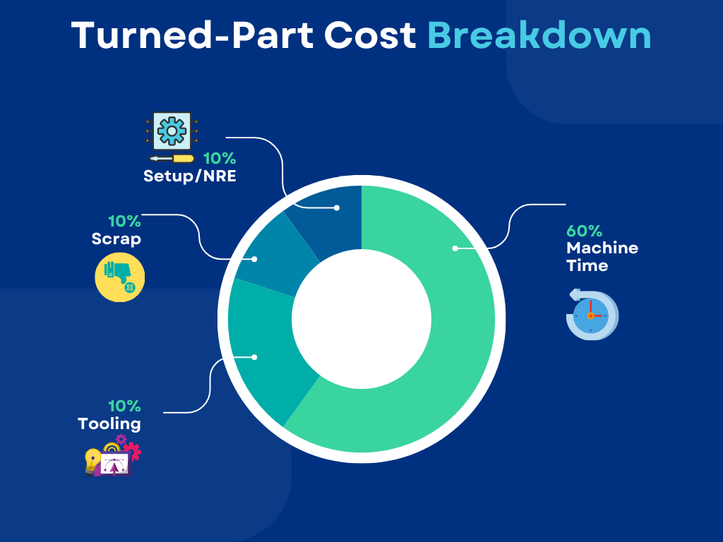
How Turned-Part Costs Are Built
A simplified model for estimating piece price:
Piece Cost ≈ (Cycle Time ÷ 60) × Machine Rate + Labor + Tooling per Part + Scrap per Part + (NRE ÷ Lot Size)
Levers Controlled by Design
- Reduce roughing & minimize passes.
- Use standard inserts & reliefs.
- Choose realistic tolerances for less scrap.
- Design for repeatable workholding.
Core DFM Principles for Turning
Keep It Symmetrical
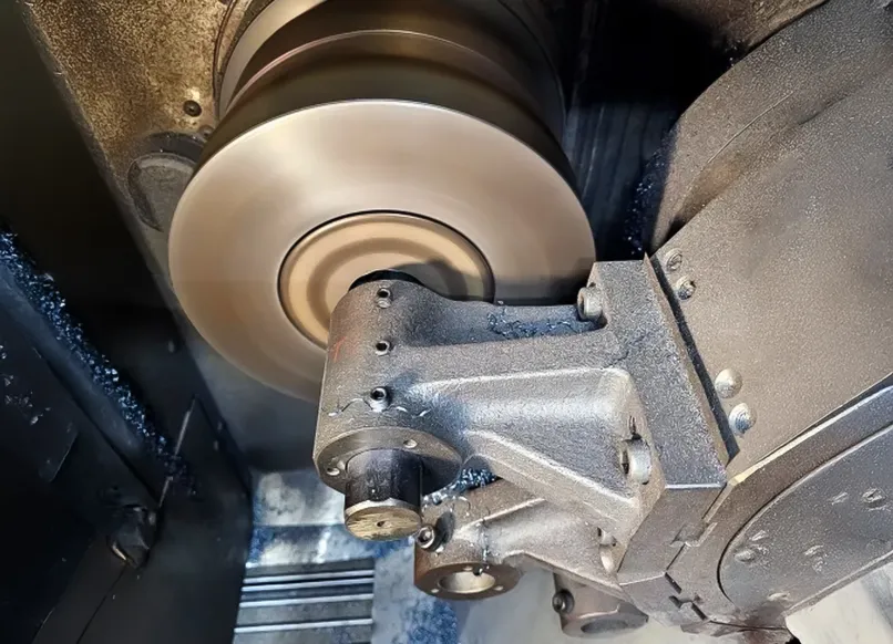
Lathes thrive on concentric geometry. Align datums to the spindle axis. Use live-tool turning for flats or side holes if positional accuracy matters. Reducing secondary ops preserves runout and lowers cost.
Standardize Diameters and Widths
Choose common diameters (0.500″, 0.750″, 1.000″, 1.250″, 1.500″).
Match groove widths to standard insert sizes. Avoid “almost” sizes.
Right-Size Tolerances
Reserve ±0.0005″ for bearing or seal surfaces. Use ±0.002″–0.005″ for non-critical ODs. Over-specifying tolerances raises costs dramatically.
Design Grooves and Undercuts for the Tool
Use catalog insert widths and depths. Leave tool clearance behind shoulders. Avoid deep or narrow grooves that cause chatter.
Respect Length-to-Diameter Ratios
External turning: support when L/D > 3:1.
Internal boring: depth ≤ 6× diameter.
Call Out Realistic Surface Finishes
Ra 16 µin for bearing surfaces, Ra 32–63 µin for general faces.
Reducing unnecessary finish specs often halves cycle time.
Threads: Use Standards and Add Relief
Stick to UN/UNF or metric pitches. Add thread relief and chamfers. Avoid threads running tight to a shoulder.
Chamfers and Lead-Ins Save Time
Add 0.010″–0.030″ × 45° chamfers on edges. Chamfers remove burrs and ease assembly.
Design for Live-Tool Consolidation
Combine turning and milling in one setup when accuracy demands. It eliminates extra chuckings and maintains true position.
Choose the Right Stock Size
Match bar OD closely to finish OD. Oversized stock wastes time and inserts.
Example: Use 1-1/16″ bar for 1.000″–1.020″ finished ODs.
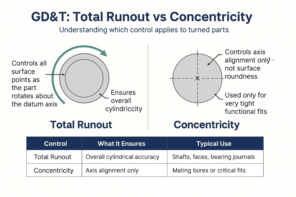
GD&T for Turned Parts
- Primary datum: rotational axis.
- Use Total Runout for cylindrical controls (simpler to measure).
- Use Concentricity only when truly required.
- Faces and Shoulders: control perpendicularity or parallelism to the axis.
Surface Finish and Tool Nose Radius
Approximation Formula:
Ra ≈ (Feed2) ÷ (32 × Nose Radius)
Implications:
- Smaller feed = smoother surface finish.
- Larger nose radius allows faster feeds at the same surface finish.
- Wiper inserts achieve low Ra values even at higher feeds (ideal for production).
Material and Bar Stock Planning
- Prefer cold-drawn or ground bar for better straightness and reduced vibration.
- Check machinability ratings — materials like 12L14, 303, and 6061 cut much faster than 1018, 304, or 7075.
- Use lead-free alternatives where regulations require.
Live-Tool and Mill-Turn: When to Consolidate
Use Live-Tooling When:
- Side holes, keyways, or flats must be accurately aligned to the spindle axis.
- Eliminating a secondary setup reduces total cost per part.
- Lot sizes are large enough to justify cycle-time tradeoffs.
Avoid Live-Tooling When:
- Heavy milling dominates the part (a stand-alone mill may be faster and more rigid).
- Features don’t need tight positional control relative to the turning axis.
Quick DFM Checklists
Drawing Review
- ✔ Primary datum = spindle axis
- ✔ Tight tolerances only on critical fits
- ✔ Standard groove/thread relief sizes
- ✔ Chamfers on edges and transitions
- ✔ Proper surface finishes
- ✔ Stock close to finished OD
- ✔ Support for long L/D parts
Supplier Quote Review
- ✔One-setup plan validated
- ✔Standardized tool library
- ✔Tool-life counters active
- ✔Setup docs with offsets/photos
- ✔SPC data on key diameters
30/60/90-Day Implementation Plan
📋
0–30 Days
Assess
Select 2–3 parts, identify tolerance & finish issues, confirm bar sizes, setup times.
🛠
31–60 Days
Engineer
Update drawings & CAM, track tool life, run pilot lots.
📈
61–90 Days
Scale
Apply improvements to families, record cycle time gains, expand SPC tracking.
Frequently Asked Questions.
Not always. Stable setups, finish passes, and correct tooling can achieve that tolerance. Grinding is only required when extreme runout or Ra ≤ 16 µin are critical
As close as availability allows. For a 1.000″–1.020″ OD, a 1-1/16″ bar minimizes roughing time and tool wear.
When it eliminates a separate setup or fixture and holds better position to the axis. For heavy milling, a vertical mill may still be faster.
External: >3:1 → use tailstock or steady rest.
Internal boring: >6× diameter → expect slower feeds or secondary ops
How Baxter Machine & Tool Helps
- DFM Reviews: We identify cost-saving design adjustments early.
- In-House Fixturing: Custom jaws and collets engineered for your part geometry.
- In-Process Verification: Probing and SPC built into every production run.
- Automation Integration: Bar feeders and live-tool setups tailored for uptime.
Send your print or model to discuss manufacturability, pricing, and potential process improvements.