

Why Machining Distortion Happens
Distortion is any unintended change in geometry—bow, twist, taper, ovality, or size drift—that appears during machining or after heat treatment.
It shows up as →
Bowed shafts
The shaft curves because internal or heat-treat stresses release unevenly along its length.
Tapered bores
The bore becomes wider at one end due to uneven stock removal, tool pressure, or heat-treat deformation.
Out-of-round journals
Circular features lose roundness when clamping pressure, heat treat, or tool forces distort the profile.
Warped flats or plates
Thin or wide surfaces bend because they cannot resist thermal, clamping, or machining-induced stresses.
Parts that move “overnight” after roughing
Residual stress inside the material relaxes over time, causing the part to shift even without further machining.
The Four Root Causes (The Distortion Quadrant)
Every distortion event in machining ties back to one or more of these four:
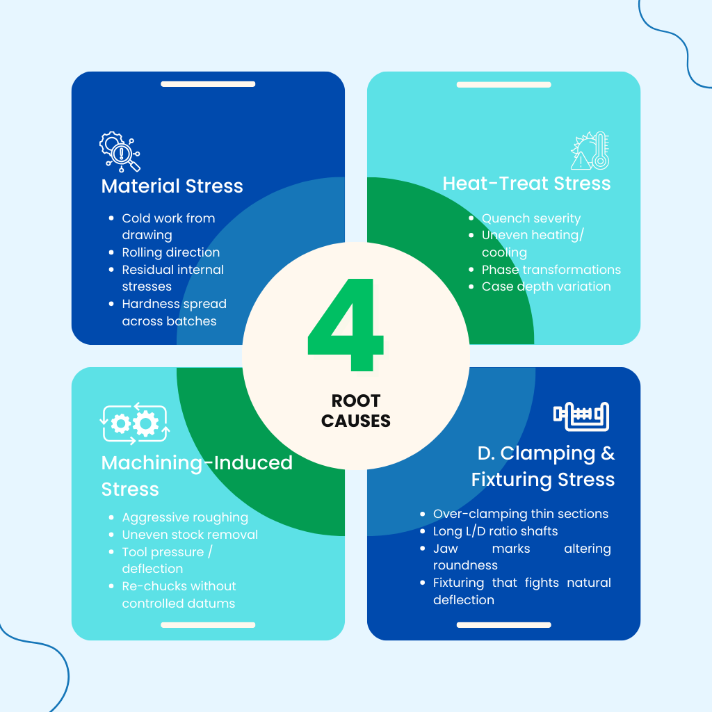
Material & Heat-Treat Control (The Silent Precision Killer)
Heat treat creates the largest, fastest, and least reversible distortion in the entire machining lifecycle.
Why heat treat causes movement?
Parts expand during heating and contract during quenching
Carbide formation and martensitic transformations change volume
Uneven case depth creates “banana bend”
Hardness inconsistency shifts cutting forces in post-HT machining
Best Practices for Distortion-Resistant Heat Treat
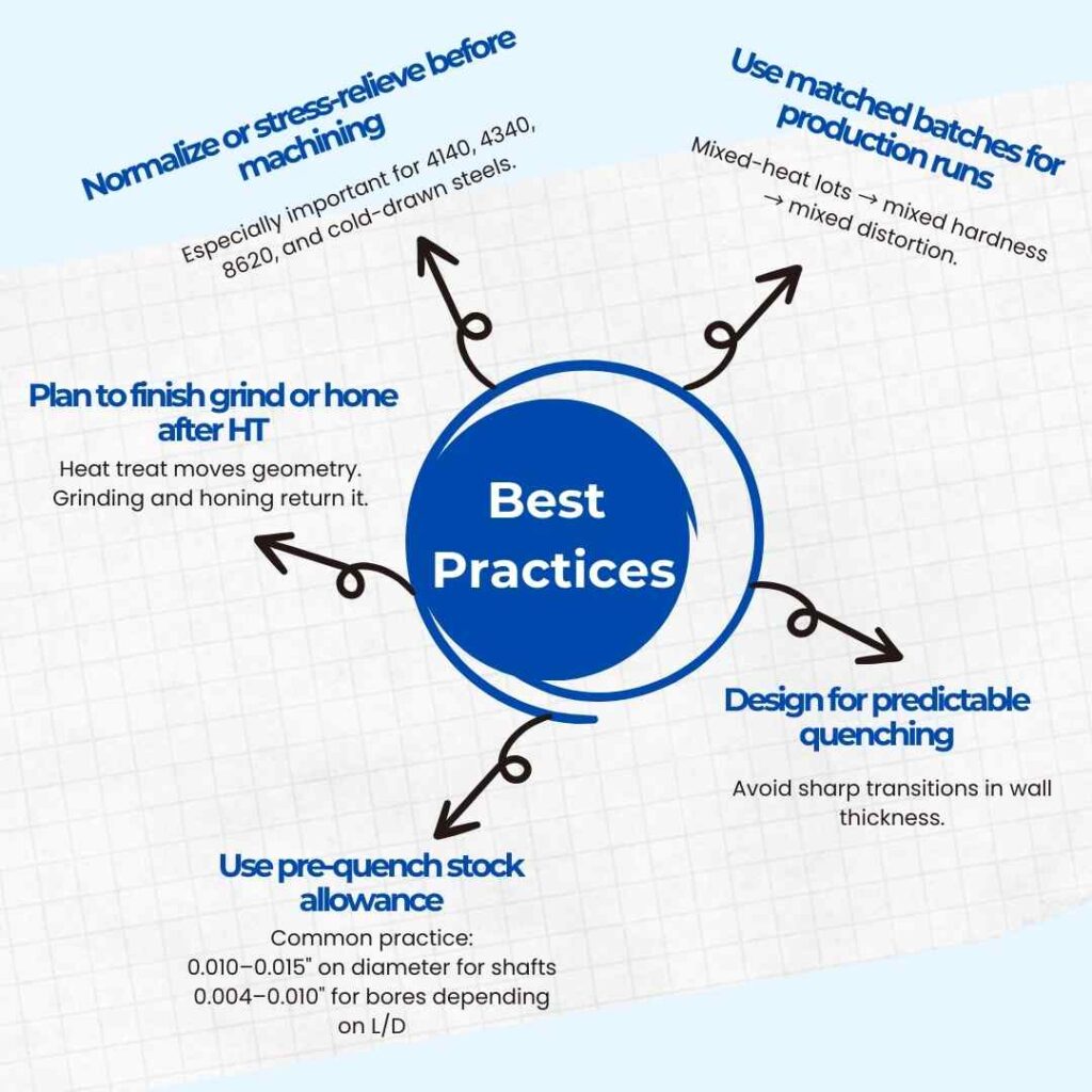
Stock Removal Strategy: Symmetry, Sequence & Stress
(Narrative → Principle → Micro-list → Callout)
-
Stock removal is where distortion quietly begins. Even before heat treat enters the picture, the way material is removed determines how internal stresses are released—or trapped—inside the part.
When machining removes material unevenly, the remaining mass attempts to rebalance itself. That rebalancing is what causes shafts to bow, bores to taper, and flat surfaces to warp later in the process.
Core principle
Distortion is rarely caused by how much material you remove — it’s caused by when and where you remove it.
What typically creates instability:
Removing heavy stock from one side before the opposite side
Aggressive roughing that spikes cutting pressure
Inconsistent depth of cut between passes
Treating roughing and finishing as the same operation
What stable stock removal looks like
Instead of chasing size early, stable processes:
Use balanced, mirrored roughing passes
Maintain consistent chip loads
Leave predictable finish stock for later correction
Protect datums by limiting re-orientation
 Fixturing, Clamping & Cutting Pressure")
Fixturing, Clamping & Cutting Pressure
Many distortion problems don’t come from material or heat treat—they come from the fixture.
A part that looks perfect in the machine can spring out of shape the moment it’s unclamped. This happens because the fixture temporarily forces the part into geometry it cannot naturally hold.
What’s really happening
- Excessive jaw pressure elastically deforms the part
- Cutting forces add bending during machining
- Once released, the part relaxes into a new shape
Common distortion triggers
- Over-clamping thin or flexible sections
- Hard jaws contacting at isolated points
- Unsupported long shafts during turning
- Finishing passes with worn or dull tools
What reduces fixturing distortion
- Soft jaws matched to part geometry
- Steady rests or tailstocks for long L/D parts
- Clamping on non-functional surfaces
- Sharp tools with stable chip formation
🔧 Rule to remember: If a part only measures good while it’s clamped, the fixture—not the part—is controlling the geometry.
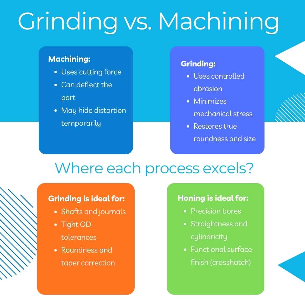
Grinding & Honing: The Geometry Reset
Once heat treat enters the process, machining alone can no longer guarantee geometric stability. Turning and milling shape material, but they also introduce force and heat—both of which can add distortion instead of removing it.
Grinding and honing serve a different role entirely: they reset geometry without re-stressing the part.
Why integration matters
When grinding and honing are outsourced, parts:
Lose datum consistency
Gain setup variation
Experience added lead time and risk
When finishing stays in-house, geometry stays controlled.
🧠 Key insight: Grinding and honing don’t “finish” distortion — they erase it.
Metrology for Distortion: Seeing the Problem
(Reality check → Trait-by-trait explanation → Measurement logic)
One of the most common mistakes in machining is assuming that size equals quality.
A part can measure perfectly on diameter and still fail in the field due to distortion that was never measured.
Why size alone is misleading?
- A micrometer averages high and low spots
- Calipers ignore form error entirely
- Go/no-go gages don’t reveal shape
Matching the tool to the distortion
- Air gages for high-resolution bore measurement
- Roundness testers for rotating features
- Indicators and V-blocks for quick bow checks
- CMMs for deeper geometric analysis
Distortion traits that actually matter
- Roundness: reveals lobing in journals
- Cylindricity: confirms bore consistency end-to-end
- Straightness: detects bow in long parts
- Taper: shows gradual size drift
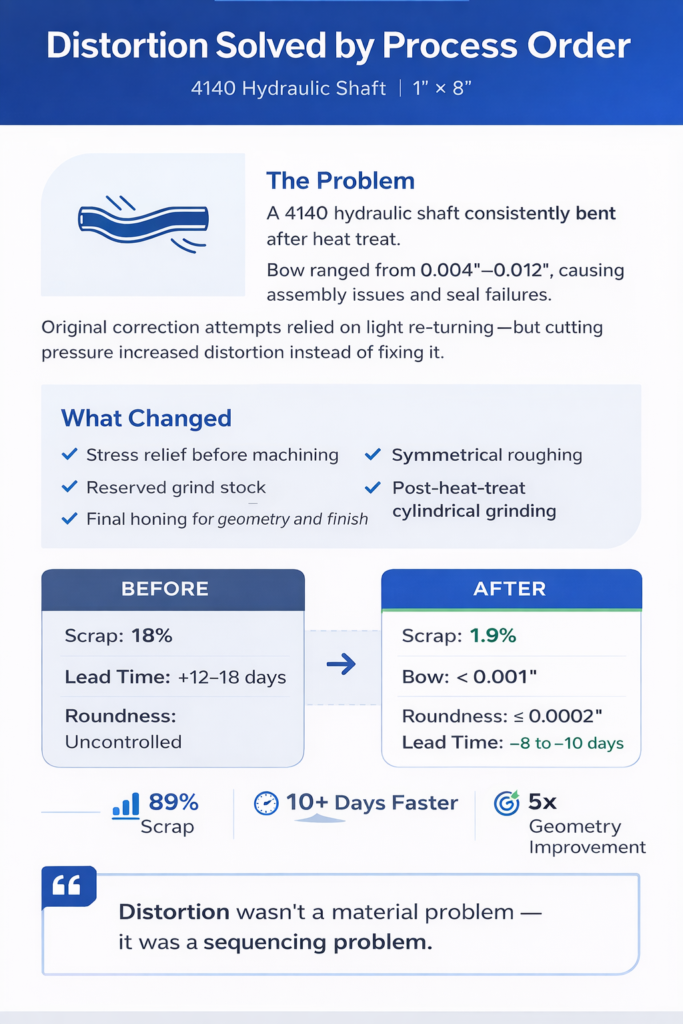
CASE STUDY
30 / 60 / 90 Day Distortion-Control Framework
End goal: Distortion becomes predictable, measurable, and preventable.
_________________________________________
0–30 Days | Diagnose
Focus on understanding where distortion enters.
- Identify distortion-prone features
- Track bow, taper, and roundness
- Review re-chucks and roughing order
31–60 Days | Engineer
Stabilize the process.
- Redesign fixturing and datum flow
- Lock rough/finish stock allowances
- Introduce grinding or honing where needed
61–90 Days | Prove & Scale
Turn fixes into standards.
- Pilot revised process
- Track Cp/Cpk and scrap
- Apply learnings to similar parts
Let’s Talk Precision
We take a process-first approach, aligning machining, heat treat, and in-house grinding and honing to control distortion and recover true geometry. With integrated metrology and production-ready process planning, we help stabilize parts from prototype through long-term production. If you have a distortion-sensitive component, share your print and functional requirements—we’ll propose a clear machining and finishing strategy with practical cost and capability trade-offs.
Stay Updated With Machining Insights
Weekly updates on machining, grinding, tolerancing, and process optimization.